


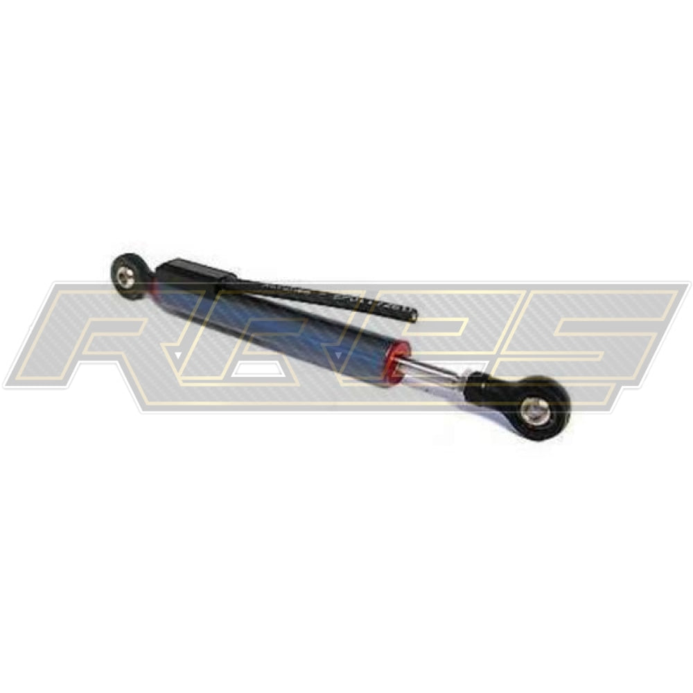
Aim Motorcycle Suspension Potentiometer Rose Joint
£263.00
The Aim Motorcycle Suspension Potentiometer Rose Joint using Aim loggers can measure the displacement between two points using a sensor (linear potentiometer) directly connected to the points of measure. This potentiometer can measure linear displacements like:
- dampers compression or extension
This is a good sensor to log when at the track. As, the Engineers can check to see how the suspension is performing when out on track. From this you can identify set-up changes such as, stiffen or loosen the suspension. This change could eliminate understeer or/ and oversteer.
- steering rotation measured through the rack displacement
Installation
When installing the sensor:
- be very careful avoiding possible bending of the internal cylinder; these bendings, occurring when over tightening the screws or in case of incorrect mounting, can seriously damage the sensor
- extract the internal cylinder for about 5 mm (0.2 inches) from the sensor lower boundary position.
- if you need to open the two pop joints use the black plastic clip ; images here above on the right show the clip closed on top and open on bottom.
Please note: do not use this sensor to measure distances beyond the potentiometer maximum travel.
The car/bike linear potentiometer can be connected to any analog channel of AiM loggers.
 Software setup – Suspensions
Once the potentiometer installed it is necessary to load it in the configuration of its logger and then calibrate/auto calibrate it.
4.1 Setup with
Race Studio 3
To load the potentiometer in the logger configuration run the software and select the configuration you are going to load it on.
 Enter the configuration (in the example MXL2 03) and the related "Channels" layer.
- Select the channel where to set the potentiometer on – in the example channel 6 (1) and fill in the panel that shows up
- Function: "Position" (2)
- Sensor: "Position Pot. AutoCal" (3 – this implies that the potentiometer will be auto-calibrated as shown in the following pages)
- Fill in the other fields
- Fill "Total Potentiometer travel" box with the potentiometer travel in mm – in the example we used a 75 mm travel potentiometer (4)
- Click "Save"
 To auto-calibrate the potentiometer:
- enter "All" layer and press "Device" (1)
- select the logger – in the example MXL2 ID 410 (2)
- in "Live Measures" layer, keeping the potentiometer in its zero position, select the channel where the potentiometer has been set – in the example channel 6 (3)
- press "Auto Calibrate" (4)

- Keep the potentiometer in its zero position as shown here below
- Press "Auto calibrate All".
